Tuesday, December 27, 2011
400W RF Power Amplifier with MOSFET FQA11N90
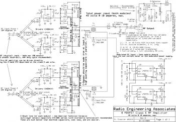
Here the 400W RF power amplifier circuit build using power MOSFET FQA11N90. This Class E RF amplifier will provide approximately 400 watts of RF output, depending on the input voltage and tuning parameters (current). The amplifier utilizes low-cost IXDD414 Driver ICs - one for each two MOSFETs. Transient Voltage Supressors (TVS devices) are applied on the gates, drain bus and modulated DC input towards the RF amplifier to secure the MOSFETs from damage because of accidental overvoltage. The carrier DC voltage ought to be between 40 volts and 50 volts, and not greater than 135 volts at full positive peak modulation.
Monday, December 19, 2011
VHF Preamplifier for FM Broadcasting 88MHz-108MHz (Band II)
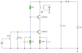
Above schematic diagram is the circuit of VHF pre-amplifier for FM broadcasting (frequency 88MHz-108MHz, band II)
The circuit is working with two 2N3819 FET's in cascode configuration. The lower FET works in common source mode, while the upper FET, works in common gate, realising full high frequency gain. The bottom FET is adjustable allowing a peak for a particular station.
Subscribe to:
Posts (Atom)

