Monday, September 26, 2011
UHF-TV Pre-Amplifier
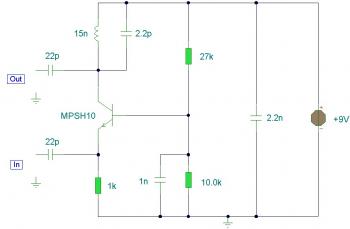
This is the another UHF-TV pre-amplifier circuit diagram which simpler than the previous UHF TV preamplifier. This circuit is based MPSH10. Alternatives that could be put to use to replace MPSH10 are BF180 and BCY90. The tuned circuit comprising the 15nH inductor and 2.2pF capacitor resonate in the center of the UHF band. The 2.2pF capacitor could be exchanged for a 4.7pF as well as a trimmer capacitor of 2-6pF for better outputs.
Thursday, September 15, 2011
18dB Channel Plus RF Amplifier
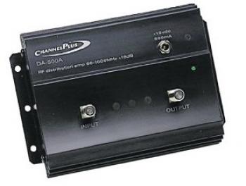
18dB Channel Plus RF amplifier best buy. This RF amplifier product offers a robust power supply and great EMI rejection. It includes grid mounting ears for the Model 2619 Rack-mount Grid. The DA-500A is fully compatible with HDTV Television signals.
Review:
The product is as it is described. It amplifies your signal before splitting it, so that you do not have any signal loss. The one thing someone must understand is that it amplifies signal that already exists, it doesn't create signal that isn't there. So if you place it at a point after it has already been split a few times, it wont do anything for you. I live in an apartment, and I guess our cable signal is not the strongest by the time it reaches our apartment. So unfortunately, I don't get the greatest signal ever.
However, when I attempted to split my signal three ways, the signal leading to my computer tv tuner turned out to be extremely degraded before I got the amplifier. Upon adding the amplifier, that signal now comes in as clear as my television does. The television signals seems to be slightly better as well, however if it is better, it is by such a small amount that i can't really say for sure that it really has improved.
This is a great device if you want to split your cable about three ways, assuming that each split causes roughly a loss of about 6.5 db. Any more splitting then that and you are going to face more signal degradation. This device can not be plugged in with your Internet, or it will cause it not to work. I had to rewire it so that my cable Internet and digital phone split before it hit the amplifier. When it was directly plugged through the amp, I lost my phone and Internet.
Besides that, it is a good device to prevent signal degradation when splitting cables. However, if you are not splitting cables and are simply trying to amplify 1 signal to 1 television, its not going to do anything for you, in fact, the only thing that would is a call to your cable company.
18dB Channel Plus RF Amplifier Product Features:
- High-power, low-noise, low-distortion RF distribution amplifier
- Flat response from 50 MHz to 1 GHz; nominal gain of 18 dB
- Suitable for off-air and unidirectional cable TV, VHF, and UHF applications
- Also appropriate for FM, Midband, Superband, Hyperband, and Ultraband uses
RF Amplifier Labels:
RF Amplifier Sale
Thursday, September 8, 2011
4W HF Bands QRP RF Linear Amplifier
HF Bands QRP RF Linear Amplifier based power transistor 2N5590.
This is a rather unusual QRP power RF amplifier design, with a wide frequency response; within three dB's from 300KHz to 30MHz. Overall gain is in the region of 16dB and the final output power may be well over four watts.
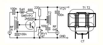
The wide bandwidth is a result of the construction of the RF transformers, T1 and T2. These are wound on 2-hole ferrite balun cores as commonly found in the old fashioned valve TV sets (e.g. Phillips 4322-020-31520). Twist 2 lengths of 22 SWG enamelled wire together and wind as shown. Connect the end of the "A" winding to the start of the "B" winding. Use this junction as the centre-tap of the transformer.
This PA will deliver 4 watts continuously (with a suitable heatsink), and may be loaded into a short-circuit or open circuit without causing damage. This makes it almost the ideal PA for outdoor/field use. Above is the full circuit diagram of the RFPA and the coil winding pattern. This PA may be used for for SSB, as well as CW (and AM?).
Set RV1 to MINIMUM resistance and apply 12volt power supply with NO DRIVE. Adjust RV1 for about 250mA DC total supply current. This may be be reduced to a much smaller current if lower output powers (reduced drive) is used.
Subscribe to:
Comments (Atom)


