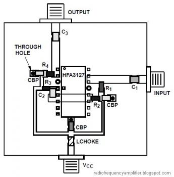
Below diagram is the RF Amplifier Design Using HFA3046, HFA3096, HFA3127, HFA3128 Transistor Arrays
This RF Amplifier document is focused on exploiting the RF design capabilities of HFA3046/3096/3127/3128 transistor arrays.
Detailed design procedures, using these transistor arrays, for a matched (800MHz to 2500MHz) high-gain low-noise amplifier and a 10MHz to 600MHz wideband feedback amplifier are described.
Download the complete application document of this RF amplifier circuit:
» Download Link
Saturday, May 28, 2011
1.5W RF Amplifier circuit
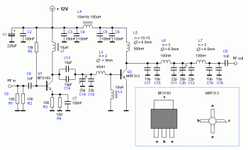
The following diagram is complete design for 1.5W RF Amplifier class C powered using power transistor BFG193 and MRF313.
Schematic Diagram:
Parts List:
R1, R2, R3, R4 = 100
R5 = 10k
C1 = 220uF
C2, C3, C4, C5, C6, C7 = 100nF
C8, C9 = 1nF
C10, C11, C12 = 22pF
C13, C14, C15, C16 = 15pF
C17, C18 = 10pF C
19, C20 =(Variable capacitor 5-25pF)
L1, L2 = 10uH
L3 = 45nH 2 turns diam 5mm (wire = 0.8mm)
L4 = 27uH (Can be 10uH-100uH)
L5 = > 500nH 10-15 turns diam 6.5mm (wire = 0.8mm)
L6, L7 = 100nH 3 turns diam 6.5mm (wire = 0.8mm)
Q1 = BFG193
Q2 = MRF313, 2N3866, 2N4427
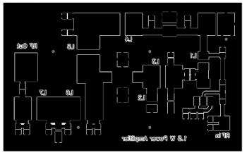
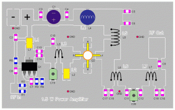
PCB Design:
Complete explanation about this RF amplifier circuit, go to this page
BLY94 - 100W RF Amplifier Circuit
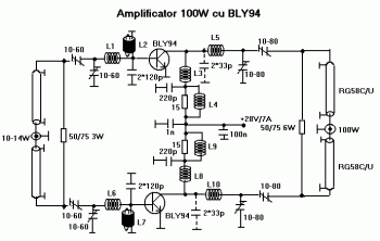
The following diagram is the circuit diagram of RF amplifier which able to deliver up to 100W radio frequency signal. The circuit built based active component BLY94.
Coaxial cable length : K x Lambda / 4, where K = 0.66 for 50 ohm cable and K = 0.8 for 75 ohm cable.
L1 = L6 = 2 turns / 1.5mm / 14mm
L2 = L7 = 8turns/0.8mm/4mm/ferite or HF
L3 = L8 = 4 turns / 2mm / 14mm / gap 1mm
L4 = L9 = 20turns/0.3mm / 3mm / ferite
L5 = L10 = 1 turn / 2mm / 15mm
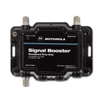
Motorola Signal Booster Bi-Directional RF Amplifier
This is a bi-directional RF amplifier signal booster manufactured by Motorola.
Make your signal strength up to 32 times more powerful in a snap, to enhance analog and digital picture quality, improves cable modem communication, and reduce lost data. This device also allows you to optimize multiple broadband devices in your home--televisions, cable set-top boxes, cable modems, VCRs, and digital radios.
Motorola Signal Booster Bi-Directional RF Amplifier Features:
Buy this RF Amplifier From AMAZON.COM
Make your signal strength up to 32 times more powerful in a snap, to enhance analog and digital picture quality, improves cable modem communication, and reduce lost data. This device also allows you to optimize multiple broadband devices in your home--televisions, cable set-top boxes, cable modems, VCRs, and digital radios.
Motorola Signal Booster Bi-Directional RF Amplifier Features:
- Improve signal strength by up to 32 times (15 dB)
- Low noise addition of only 3 dB
- Superb gold patented connector design
- Supports Pay-Per-View and Video on Demand (VOD) Services
- Quick, easy installation
Buy this RF Amplifier From AMAZON.COM
Subscribe to:
Posts (Atom)
