Tuesday, January 31, 2012
10W Linear RF Amplifier Circuit
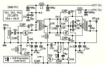
This is the 10W linear RF amplifier circuit whish use 2SC2078 as the main component to power up the input signal. The circuit actually can delivers output signal up to 15W.
This RF amplifier circuit has a wide bandwidth range, from 1.8 MHz through to over 30 MHz. The drive level needed is only about 2 - 5 mW under 14 MHz, increasing to 10 mW at 30 MHz. You can therefore make a good QRP CW rig with nothing more than this PA and a simple crystal oscillator. I can achieve 12 watts out of mine using a 10-turn loop around my Grid Dip Oscillator! I can get over 15 watts from my Marconi signal generator, but above about 12 watts it is being over-driven an may not be very nice to look at on the spectrum analyser. The circuit was designed to be as clean as possible.
Monday, January 23, 2012
VHF RF Preamp 100-175 MHz with MAX2633
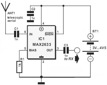
This is the diagram of VHF RF Preamp circuit 100-175 MHz with single chip MAX2633. The circuit can be used for the entire VHF broadcast and PMR band (100-175 MHz) which can be easily construct without any special test equipment. The grounded-gate configuration is inherently stable without any neutralization if appropriate PCB layout techniques are employed. The performance of the amplifier is quite good. The noise figure is below 2 dB and the gain is over 13 dB.
Tuesday, January 17, 2012
Low-Cost Broadband HF Amplifier based MOSFET IRF510
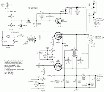
This is the circuit diagram of low-cost broadband HF amplifier build based MOSFET IRF510. The amplifier is built on double-sided PC board and requires no tuning. Another PC board contains the low-pass filters. Power supply needed for this RF amplifier is 28 V DC at 5 A, although the amplifier performs well at 13.8 V DC.
Several of these amplifiers have been built and exhibit similar performance. Al has been using his amplifier on each of the HF bands, logging well over 500 contacts in 18 months. Signal reports indicate a noticeable improvement in readability (about two S units on average) over his 5 W rig. No indications of instability, CW key clicks or distortion on SSB have been reported. To make it easy for you to duplicate this project, PC boards and parts kits are available, all at a cost of about $100!
Several of these amplifiers have been built and exhibit similar performance. Al has been using his amplifier on each of the HF bands, logging well over 500 contacts in 18 months. Signal reports indicate a noticeable improvement in readability (about two S units on average) over his 5 W rig. No indications of instability, CW key clicks or distortion on SSB have been reported. To make it easy for you to duplicate this project, PC boards and parts kits are available, all at a cost of about $100!
Thursday, January 12, 2012
12W RF Amplifier 88-108 MHz based RD15HVF1
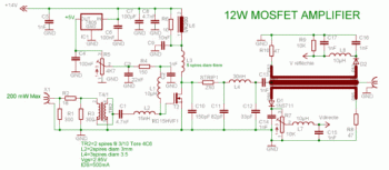
This is the 12W RF amplifier circuit for frequency range of 88MHz to 108MHz (FM broadband). This new FM power amplifier is used the famous MOSFET RD15HVF1. We've chosen the synthesizer N°1 to drive this amplifier circuit. In fact, only 200mW are required to obtain the 12W output power level.
Wednesday, January 4, 2012
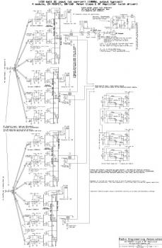
Class E RF Amplifier with 24 MOSFETs
This is the circuit diagram of Class E RF Amplifier which build using total of 24 MOSFETs. This high power RF amplifier covering the 80 and 160 meter amateur radio bands.
The amplifier is constructed in 4 of 6-MOSFET modules and applies IXDD414 digital gate drivers. Every gate driver drives 2 MOSFETs.
Subscribe to:
Posts (Atom)
