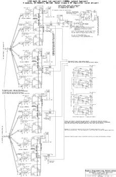
This is the circuit diagram of Class E RF Amplifier which build using total of 24 MOSFETs. This high power RF amplifier covering the 80 and 160 meter amateur radio bands.
The amplifier is constructed in 4 of 6-MOSFET modules and applies IXDD414 digital gate drivers. Every gate driver drives 2 MOSFETs.
A single 1500pF multilayer ceramic capacitor is applied per module as the shunt capacitor when operating on 80 meters. An extra 1500pF capacitor is switched in (working with small relays) when operating on the 160 meter band.
Two coils are implemented, one for 80 meters and an extra coil for 160 meters, that is shorted out by a relay when operating on 80 meters.
The tuning capacitor has enough range to cover the two bands. Two loading capacitors are utilized to give enough capacitance for 160 meters. A constant capacitor may also be chosen, if the device can deal with the high RF current.
Download the schematic diagram in PDF file (large image):
» Download link
Class E RF amplifier with 24 MOSFETs, page source: classeradio.com. Go there for the complete circuit documentation.
About RF Amplifier
An RF power amplifier is a type of electronic amplifier which is utilised to convert a low-power radio-frequency signal into a larger signal of significant power, usually for driving the antenna of a transmitter. It is usually optimized to have high efficiency, high output Power (P1dB) compression, good gain, good return loss on the input and output, and optimum heat dissipation.
The basic applications of the RF power amplifier include driving to another high power source, driving a transmitting antenna, microwave heating, and exciting resonant cavity structures. Among these applications, driving transmitter antennas is most well known.
More explanation about power audio amplifier can be found at wikipedia.org
This is a demonstration about 01A RF Amplifier which is build used old tube component to amplify the signal. An RF power amplifier is a type of electronic amplifier which is utilised to convert a low-power radio-frequency signal into a larger signal of significant power, usually for driving the antenna of a transmitter. It is usually optimized to have high efficiency, high output Power (P1dB) compression, good gain, good return loss on the input and output, and optimum heat dissipation.
The basic applications of the RF power amplifier include driving to another high power source, driving a transmitting antenna, microwave heating, and exciting resonant cavity structures. Among these applications, driving transmitter antennas is most well known.
More explanation about power audio amplifier can be found at wikipedia.org
Watch the video:

No comments:
Post a Comment