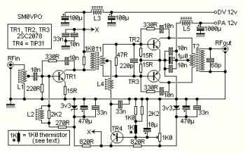
This is the 10W linear RF amplifier circuit whish use 2SC2078 as the main component to power up the input signal. The circuit actually can delivers output signal up to 15W.
This RF amplifier circuit has a wide bandwidth range, from 1.8 MHz through to over 30 MHz. The drive level needed is only about 2 - 5 mW under 14 MHz, increasing to 10 mW at 30 MHz. You can therefore make a good QRP CW rig with nothing more than this PA and a simple crystal oscillator. I can achieve 12 watts out of mine using a 10-turn loop around my Grid Dip Oscillator! I can get over 15 watts from my Marconi signal generator, but above about 12 watts it is being over-driven an may not be very nice to look at on the spectrum analyser. The circuit was designed to be as clean as possible.
This circuit was originally designed to accompany my phasing-type SSB exciter, but it can be used to amplify almost any HF signal from 2mW in the HF band. Note that there is needed a Low-Pass filter between the amplifier and antenna. This is a requirement for ALL transmitters.
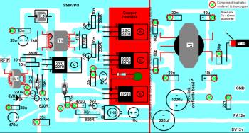
PCB Layout design:
More explanation about this 10W linear RF amplifier circuit, visit this page
About RF Amplifier
An RF power amplifier is a type of electronic amplifier which is utilised to convert a low-power radio-frequency signal into a larger signal of significant power, usually for driving the antenna of a transmitter. It is usually optimized to have high efficiency, high output Power (P1dB) compression, good gain, good return loss on the input and output, and optimum heat dissipation.
The basic applications of the RF power amplifier include driving to another high power source, driving a transmitting antenna, microwave heating, and exciting resonant cavity structures. Among these applications, driving transmitter antennas is most well known.
More explanation about power audio amplifier can be found at wikipedia.org
This is a demonstration about 01A RF Amplifier which is build used old tube component to amplify the signal. An RF power amplifier is a type of electronic amplifier which is utilised to convert a low-power radio-frequency signal into a larger signal of significant power, usually for driving the antenna of a transmitter. It is usually optimized to have high efficiency, high output Power (P1dB) compression, good gain, good return loss on the input and output, and optimum heat dissipation.
The basic applications of the RF power amplifier include driving to another high power source, driving a transmitting antenna, microwave heating, and exciting resonant cavity structures. Among these applications, driving transmitter antennas is most well known.
More explanation about power audio amplifier can be found at wikipedia.org
Watch the video:


No comments:
Post a Comment