Wednesday, June 29, 2011
AM RF Amplifier Circuit for External Antenna
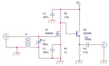
This is an AM RF Amplifier Circuit for External Antenna which built using RCA 40468A FET. The detailed explanation and recomendation about this circuit, go to this page.
Saturday, June 25, 2011
10dB VHF/UHF/FM Signal Amplifier
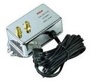
This is one of RF amplifier application which will boost the signal received by antenna. The circuit will boost UHF, VHF and FM signal. Nice choice for radio receiver and television.
10dB VHF/UHF/FM Signal Amplifier Features:
10dB VHF/UHF/FM Signal Amplifier Review:
We recently cut our ties with DirecTV and just went with more than the air digital signal. The RCA outside antenna worked great, but sometimes the picture pixelated. Getting study critiques and experiences of other people, I bought this signal amplifier and was blown away by the difference this little device made. We had extremely good HD quality, but this created it even better AND we found 4 much more stations that we weren't obtaining prior to utilizing this.
Better picture, no pixelation and much more channels! Great Deal!
Buy 10dB VHF/UHF/FM Signal Amplifier from Amazon.Com
10dB VHF/UHF/FM Signal Amplifier Features:
- Increases VHF/UHF/FM signals by 10dB
- Compensates for signal loss/weak signal that occurs during long cable runs or multiple TV/VCR connections
- For use with both RG6 and RG59 coaxial cables
10dB VHF/UHF/FM Signal Amplifier Review:
We recently cut our ties with DirecTV and just went with more than the air digital signal. The RCA outside antenna worked great, but sometimes the picture pixelated. Getting study critiques and experiences of other people, I bought this signal amplifier and was blown away by the difference this little device made. We had extremely good HD quality, but this created it even better AND we found 4 much more stations that we weren't obtaining prior to utilizing this.
Better picture, no pixelation and much more channels! Great Deal!
Buy 10dB VHF/UHF/FM Signal Amplifier from Amazon.Com
RF Amplifier Labels:
RF Amplifier Sale
Wednesday, June 22, 2011
500W 27Mhz RF Amplifier Circuit
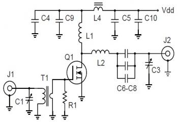
The following circuit is the 500W 27Mhz RF Amplifier circuit. The circuit build based MOSFET APT ARF448A, will give you very high gain for signal with frequency of 27MHz.
Schematic Diagram:
Parts List:
C1,C3 = 75-380 pF mica trimmer, ARCO 465
C4-C8 = .01 uF 1 kV disc ceramic
C9,C10 = .1 uF 500V disc ceramic
L1 = 6 uH. 25t #24 ga.enam. 0.5" dia.
L2 = 210 nH. 4t #8 ga. .75" id, 1" long
L4 = 2t #20 PTFE on .5" ferrite bead m=850
Q1 = APT ARF448A
R1 = 25W 5W non-inductive
T1 = Pri: 4t #20 PTFE, Sec: 1t brass tube on 2 hole balun bead. Fair-Rite #2843010302 m=850
High voltage MOSFETs are now available that combine the best practices from the RF world with the economy of the switchmode devices and packaging. They are available in mirror image pairs and the heat spreader of the plastic TO-247 package is connected to the source.
Download the aplication note for this circuit 500W 27Mhz RF Amplifier HERE
Sunday, June 19, 2011
500W High Frequency Amplifier
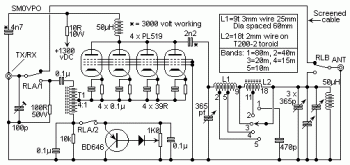
The following diagram is the circuit diagram of a 500 watt linear amplifier, based upon a design by Frits Geerligs, PA0FRI.
The circuit uses four PL519 Television line output valves inside a very simple circuit that will deliver above 450 watts at 3.5 MHz (350 watts at 30 MHz). PL519 (40KG6A) is a far more robust substitute for the earlier PL509 (40KG6) tube. Each valves will do the job properly in this circuit. The input drive power is about 50 - 100 watts so it really is working with most amateur radio HF transmitters. Not shown in the circuit will be the cooling fan that is needed to force air across the valves to cool them. In operation the 1K0 pot is adjusted to set the complete valve anode electric current to close to 50mA to 70 mA.
Detailed explanation : go to this page
Tuesday, June 14, 2011
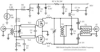
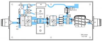
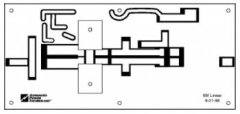
50MHz 300W MOSFET Amplifier Circuit
The following is the circuit of RF amplifier based on MOSFET. This amplifier will deliver very high power of 300W for radio frequency of 50MHz-51Mhz.
Schematic Diagram:
The component part list for this RF amplifier circuit, you can check inside the 50MHz 300W MOSFET Amplifier Circuit document.
Component Placement:
PCB Layout:
Technical Details:
Download 50MHz / 300W MOSFET Amplifier Circuit complete document HERE
Schematic Diagram:
The component part list for this RF amplifier circuit, you can check inside the 50MHz 300W MOSFET Amplifier Circuit document.
Component Placement:
PCB Layout:
Technical Details:
- Frequency range: 50 to 51 MHz
- Input VSWR: < 1.5:1
- Gain: >13 dB
- Output Power: 300 W PEP or CW
- Efficiency: > 50%
- IMD3: < -25 dB below PEP
Download 50MHz / 300W MOSFET Amplifier Circuit complete document HERE
Thursday, June 9, 2011
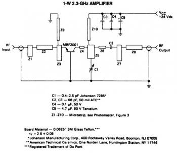
1 Watt 2.3GHz RF Amplifier Circuit
Below circuit diagram is an 1 Watt RF amplifier circuit for frequency 2.3GHz
Simplicity and repeatibility are featured in this 1 Watt S-band amplifier circuit. The circuit used a common-base power transistor MRF2001, a class C amplifier. This RF amplifier delivers about 1 Watt power output with 8-dB minimum gain at 24V voltage supply. The frequency can be tuned from 2.25GHz to 2.35GHz
Complete explanation and how to build this 1 Watt RF Amplifier, go to this page.
Sunday, June 5, 2011
2W 23cm TX ATV Transmitter
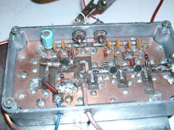
TX ATV Transmitter PCB and box
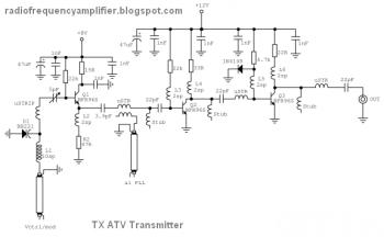
2W 23cm TX ATV Transmitter schematic diagram:
TX ATV Transmitter circuit source: http://electronics-diy.com/electronic_schematic.php?id=793
2W 23cm TX ATV Transmitter schematic diagram:
TX ATV Transmitter circuit source: http://electronics-diy.com/electronic_schematic.php?id=793
Wednesday, June 1, 2011
2W RF Amplifier
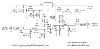
The following diagram is the schematic diagram of the microstrip single stage RF amplifier.
The RF amplifier is designed based on the M/A-Com LF2810A MOSFET. The transistor is basically a 10 watt, 28 volt part, but supplies sufficient gain for this application at 12 VDC. The amplifier delivers higher than 40% of efficiency in the desired output capability. Trimmer capacitors are applied for input and output matching. Output power is altered by a trimmer potensiometer (trimpot) which sets the gate bias voltage.
RF Amplifier circuit source: http://www.ham-radio.com/wb6zsu/components/exciter/exciter_mods.html
Subscribe to:
Comments (Atom)
