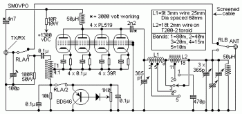
The circuit uses four PL519 Television line output valves inside a very simple circuit that will deliver above 450 watts at 3.5 MHz (350 watts at 30 MHz). PL519 (40KG6A) is a far more robust substitute for the earlier PL509 (40KG6) tube. Each valves will do the job properly in this circuit. The input drive power is about 50 - 100 watts so it really is working with most amateur radio HF transmitters. Not shown in the circuit will be the cooling fan that is needed to force air across the valves to cool them. In operation the 1K0 pot is adjusted to set the complete valve anode electric current to close to 50mA to 70 mA.
Detailed explanation : go to this page
About RF Amplifier
An RF power amplifier is a type of electronic amplifier which is utilised to convert a low-power radio-frequency signal into a larger signal of significant power, usually for driving the antenna of a transmitter. It is usually optimized to have high efficiency, high output Power (P1dB) compression, good gain, good return loss on the input and output, and optimum heat dissipation.
The basic applications of the RF power amplifier include driving to another high power source, driving a transmitting antenna, microwave heating, and exciting resonant cavity structures. Among these applications, driving transmitter antennas is most well known.
More explanation about power audio amplifier can be found at wikipedia.org
This is a demonstration about 01A RF Amplifier which is build used old tube component to amplify the signal. An RF power amplifier is a type of electronic amplifier which is utilised to convert a low-power radio-frequency signal into a larger signal of significant power, usually for driving the antenna of a transmitter. It is usually optimized to have high efficiency, high output Power (P1dB) compression, good gain, good return loss on the input and output, and optimum heat dissipation.
The basic applications of the RF power amplifier include driving to another high power source, driving a transmitting antenna, microwave heating, and exciting resonant cavity structures. Among these applications, driving transmitter antennas is most well known.
More explanation about power audio amplifier can be found at wikipedia.org
Watch the video:

No comments:
Post a Comment