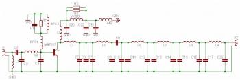
This FM power amplifier is build using a bipolar transistor MRF317. Similar to a lots of FM amplifier application, the power transistor is in a C class bias.
All the impedance networks (Input & Output) have been determined by using the Mimp software. A 9 elements low pass filter ensures that we meet at least a 60 dB rejection from the carrier (RF Simulation with RFSIM99). The FM RF amplifier has a 10 dB gain with a 60 to 65% efficiency. The Input VSWR is around 1.4 and there's no problem to reach the maximum power in all the FM band.
100W FM Amplifier Circuit source: radioinitiation.chez-alice.fr
About RF Amplifier
An RF power amplifier is a type of electronic amplifier which is utilised to convert a low-power radio-frequency signal into a larger signal of significant power, usually for driving the antenna of a transmitter. It is usually optimized to have high efficiency, high output Power (P1dB) compression, good gain, good return loss on the input and output, and optimum heat dissipation.
The basic applications of the RF power amplifier include driving to another high power source, driving a transmitting antenna, microwave heating, and exciting resonant cavity structures. Among these applications, driving transmitter antennas is most well known.
More explanation about power audio amplifier can be found at wikipedia.org
This is a demonstration about 01A RF Amplifier which is build used old tube component to amplify the signal. An RF power amplifier is a type of electronic amplifier which is utilised to convert a low-power radio-frequency signal into a larger signal of significant power, usually for driving the antenna of a transmitter. It is usually optimized to have high efficiency, high output Power (P1dB) compression, good gain, good return loss on the input and output, and optimum heat dissipation.
The basic applications of the RF power amplifier include driving to another high power source, driving a transmitting antenna, microwave heating, and exciting resonant cavity structures. Among these applications, driving transmitter antennas is most well known.
More explanation about power audio amplifier can be found at wikipedia.org
Watch the video:

No comments:
Post a Comment