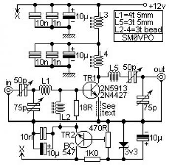
These circuits may be utilised to amplify RF power signals, from 50MHz to 170MHz, just a couple of component modifications are necessary. The circuit diagram shown are "normalised" for 100MHz and will tune about 80MHz via to 120MHz. Simply scale the components up or down if you want to go down or up in frequency bands. The circuits as shown will give a acquire of about 14dB with an output power of about two Watts (input = 100mW). With an output power of 20 watts the acquire falls off to just 12dB at 100MHz or just 10dB at 170MHz.
L3 can be a massive RF choke, produced utilizing generally 20 turns of 22SWG wire in a ferrite ring. The wire have to be thick enough to carry the PA existing. For low powers a smaller ferrite is extra than sufficient. Do not scale this inductor for other frequencies.
L4 is created working with typically 3 or four turns of 22SWG enamelled wire inside a two ferrite beads side-by-side, as a pair of biniculars. For greater powers you should ideally use a bigger two-hole binocular ferrite core.
L2 is typically 4 turns of "thin" wire on a single ferrite bead for all frequency bands.
L1 and L5 are each close-wound 22SWG enamelled wire on an air-cored 5mm Dia. former. L1 and L5 need to physically be mounted as far away from one another as feasible and in a diverse plane (if one is vertical the other ought to be horizontal).
The 50pf and 75pf preset caps might be any old caps for low power work, but above about 1 watt you ought to choose high-power rated components.
The optional resistor within the emitter will restrict the maximum output power by reducing the gain of the complete amplifier. This resistor should be commonly 12 ohms for low power devices, which include the 2N3866 or 2N4427 devices. For BLW90 or other high-power devices the emitter resistor need to be a total short-circuit. In this event the power supply must also be protected having a fuse. In high-power circuits do not use relay switching or you might burn out relays. The circuit must not draw any important present with no signal. The 18 ohm resistor really should also be reduced for power devices, generally 5R6 for a 20W amplifier.
We have added TR2 to present the 0.7vDC bias inside the form of a basic series regulator. For driving modest transistors like the 2N3866 and 2N4427, TR2 can be a very simple BC547 or a 2N2222. For driving greater power amplifiers you must use a bigger transistor fitted having a heatsink. A 2N3053 or BCY51 device must be fine. Just before switching on the major DC power to the amplifier, set the bias potentiometer to minimum voltage, apply the power and adjust the pot until TR1 draws a bit present. For 500mW to 5 watt devices it is best to set TR1 current to about 5mA to 50mA. With five watt to 25W amplifiers you ought to set the TR1 existing to about 50mA to 200mA. Do not be to mean using the standing DC present as it truly is this that's keeping the FCC of your back by giving you a clean transmission (assuming you have got a license). Now you are able to align the complete Linear PA.
2W VHF linear amplifier circuit source: sm0vpo.com
About RF Amplifier
An RF power amplifier is a type of electronic amplifier which is utilised to convert a low-power radio-frequency signal into a larger signal of significant power, usually for driving the antenna of a transmitter. It is usually optimized to have high efficiency, high output Power (P1dB) compression, good gain, good return loss on the input and output, and optimum heat dissipation.
The basic applications of the RF power amplifier include driving to another high power source, driving a transmitting antenna, microwave heating, and exciting resonant cavity structures. Among these applications, driving transmitter antennas is most well known.
More explanation about power audio amplifier can be found at wikipedia.org
This is a demonstration about 01A RF Amplifier which is build used old tube component to amplify the signal. An RF power amplifier is a type of electronic amplifier which is utilised to convert a low-power radio-frequency signal into a larger signal of significant power, usually for driving the antenna of a transmitter. It is usually optimized to have high efficiency, high output Power (P1dB) compression, good gain, good return loss on the input and output, and optimum heat dissipation.
The basic applications of the RF power amplifier include driving to another high power source, driving a transmitting antenna, microwave heating, and exciting resonant cavity structures. Among these applications, driving transmitter antennas is most well known.
More explanation about power audio amplifier can be found at wikipedia.org
Watch the video:

No comments:
Post a Comment