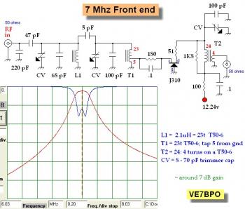
This is the schematic diagram of 40M band RF preamp with 3 tuned filters. Above image is an experimenter's 40 Meter band front end for CW. This has a double-tuned filter and a low gain, lower noise RF amplifier. This is a great circuit for isolation of a product detector or mixer in a popcorn receiver.
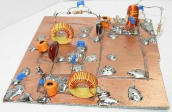
The second image is 40 meter band front end, double-tuned filter plus tuned common gate RF amplifier, they are already constructed on a single side PCB. Input and output Z is 50 ohms.
40M band RF preamp with 3 tuned filters, circuit diagram source page: www.qrp.pops.net
About RF Amplifier
An RF power amplifier is a type of electronic amplifier which is utilised to convert a low-power radio-frequency signal into a larger signal of significant power, usually for driving the antenna of a transmitter. It is usually optimized to have high efficiency, high output Power (P1dB) compression, good gain, good return loss on the input and output, and optimum heat dissipation.
The basic applications of the RF power amplifier include driving to another high power source, driving a transmitting antenna, microwave heating, and exciting resonant cavity structures. Among these applications, driving transmitter antennas is most well known.
More explanation about power audio amplifier can be found at wikipedia.org
This is a demonstration about 01A RF Amplifier which is build used old tube component to amplify the signal. An RF power amplifier is a type of electronic amplifier which is utilised to convert a low-power radio-frequency signal into a larger signal of significant power, usually for driving the antenna of a transmitter. It is usually optimized to have high efficiency, high output Power (P1dB) compression, good gain, good return loss on the input and output, and optimum heat dissipation.
The basic applications of the RF power amplifier include driving to another high power source, driving a transmitting antenna, microwave heating, and exciting resonant cavity structures. Among these applications, driving transmitter antennas is most well known.
More explanation about power audio amplifier can be found at wikipedia.org
Watch the video:


No comments:
Post a Comment